The ALU_A Arithmetic card will without doubt be one of the busiest and most complex cards I’ll have to build. The goal is to design a card that can support the following operations:
- Addition B+C
- Subtraction B-C,
- Increment B
- Increment C
- Decrement B
- Decrement C
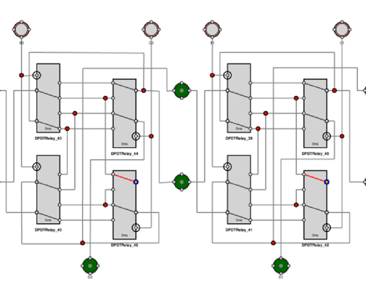
The diagram below shows the outline of the ALU_A logic. I have only included the logic for bits 0,1 and 11 for simplicity.
!
There are three groups of relays to be controlled and a logic line.
- The Green relays control If the B-Bus or C-Bus is connected to the first input of each adder.
- The Red relays control if the C-Bus OR if the static value of 1 (0000 000 0001) is connected to the second input of each adder.
- The Blue relays are used to gate the result of the adder operation onto the Data Bus.
- The final control line is the Orange ADD/SUB control line.
Addition#
Addition is fairly straight forward. To add B+C the B-Bus is connected to the adder via the Green relays The C-Bus is connected the adder via the Red Relays. The Orange ADD/SUB Line is a 0 signalling an addition operation.
I’ll explain more about what the XOR gates do later in the article - but for now think of the XOR gates as a switchable Inverter. In the case of our addition this inverter is disabled and the B-BUS passes straight through XOR gates. Finally you will also notice that the carry in to the first full adder will also be a 0 because the ADD/SUB line is also 0.
The Adder’s will then compute B+C and the result will be gated onto the data bus via the BLUE gating relays.
The state of last adders carry out will be stored in the CY condition Register.
Increment B#
The GREEN Relays will connect the B-BUS to the adders in the same way as for addition. The ADD/SUB line will also be a 0 as before. To Increment B we have to switch the Red relay’s over to the static value of 1 (0000 0000 0001). So we are now adding B+1 - Incrementing B.
Increment C#
To Increment C we switch the Green Relays over to connect to the first input of the adder to the C-BUS. We also have the RED relays switched to the static value of 1 (0000 0000 0001). So we now get C+1 - Incrementing C.
Subtraction#
Subtraction can be performed by adding the Two’s compliment of one number to the second number and adding 1.
To convert the first number into the adder we have to first make it a two’s compliment of itself, basically inverting it. so with the ADD/SUB line now 1 the XOR Gates will now act as an inverter. For reference here’s the Truth table for an XOR gate:
| A | B | X |
|---|---|---|
| 0 | 0 | 0 |
| 0 | 1 | 1 |
| 1 | 0 | 1 |
| 1 | 1 | 0 |
Here we can see that if the A input of the XOR gate is driven by the ADD/SUB control line we get this switchable inverter effect between the B input and the X output.
The next thing we have to do is add 1, this is easy so we just feed the carry in of the first inverter with the ADD/SUB line.
The last thing we need it to know if the result is negative. This is accomplished by the Inverter and the AND Gate. If the carry out bit from the last adder is 0 AND it’s a subtraction operation the SN (Sign) bit will be set in the condition register.
Decrement B and C#
These operations are identical to the Increment operation when it comes to selecting what data feeds the input of the adders.
Control Logic#
So there we are, six mathematical functions using a single adder block!
We can describe a logic table of all the inputs and the functions:
| B/C Relays (Green) | C / 1 Relays (Red) | ADD/SUB (Orange) | Function |
|---|---|---|---|
| 0 | 0 | 0 | B+C Addition |
| 0 | 0 | 1 | B-C Subtraction |
| 0 | 1 | 0 | Increment B |
| 0 | 1 | 1 | Decrement B |
| 1 | 0 | 0 | UNUSED |
| 1 | 0 | 1 | UNUSED |
| 1 | 1 | 0 | Increment C |
| 1 | 1 | 1 | Decrement C |
Practical considerations#
This will take a lot of relays and board space. My current plan will be to split the board into a base card and a daughter board. The base card will manage the control logic, Input selection, XOR ‘inverter’s’ and gating back to the data bus. The daughter board will be dedicated to the Adder logic, it will only have the two selected bus inputs, the result output, the first carry in and the last carry out. This will make it far easier to debug the ALU as a whole if I can split it operations over the two cards .